CCIE Dumps CCIE Dumps CCIE Dumps CCIE Dumps CCIE Dumps CCIE Dumps CCIE Dumps
Network Freshmen Can Rapidly Construct Small Business Network with Routing between Vlans-CCIE Dumps
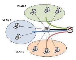
I believe many friends have already know what is vlan. But due to the isolation of the broadcast domain, the host can’t directly communicate between different vlans. So today we are going to study how to make the hosts between different vlans able to visit each other.
First to answer the beginners`question: Why yesterday we just learned how to hinder it connected between hosts by dividing vlan,but let them communicate today?
If at first it is to keep communication between these hosts, whta`s the meaning of dividing vlan?
That`s because when the network equipment are enormous, our second layer in the network will be filled with a lot of radio messages. You can imagine when thousands of devices send ARP broadcast together, switches are busy in broadcasting flood not to have time to deal with our normal data traffic, which will be a waste of hardware resources. So one of the most basic roles for vlan is to separate broadcast domain—with vlan to limit the scope of our broadcast, and then using three-layer technology to communicate between different vlans, so as to solve large-scale network broadcast messages too many to take up more resources.
Let`s start our today’s test.
Experiment 1: using single-arm routing to implement the communication between vlans
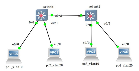
The topology:
The basic configuration:

switch1(config)#vlan 10
switch1(config-vlan)#vlan 20
switch1(config-vlan)#exit //build vlan10 and vlan20
switch1(config)#interface e0/0
switch1(config-if)#switchport mode access
switch1(config-if)#switchport access vlan 10
switch1(config-if)#exit
switch1(config)#interface e0/1
switch1(config-if)#switchport mode access
switch1(config-if)#switchport access vlan 20
switch1(config-if)#exit //Put the corresponding interface to the corresponding vlan
switch1(config)#interface e0/2
switch1(config-if)#switchport trunk encapsulation dot1q
switch1(config-if)#switchport mode trunk
switch1(config-if)#exit //Sets the link between the two switches to a trunk link
Switch2`s configuration is the same as switch1, such as in vlan10 PC using 192.168.1.0/24 network segment, and in vlan20 using 192.168.2.0/24 network segment. What`s more, their gateway address is 192.168 x. 254.
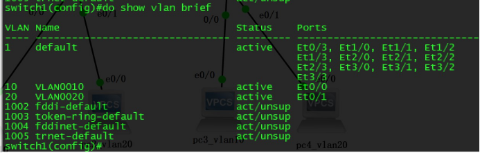
Verifying configuration:
Using “show vlan brief” command to verify whether the corresponding vlan is created and the corresponding interface is correct.
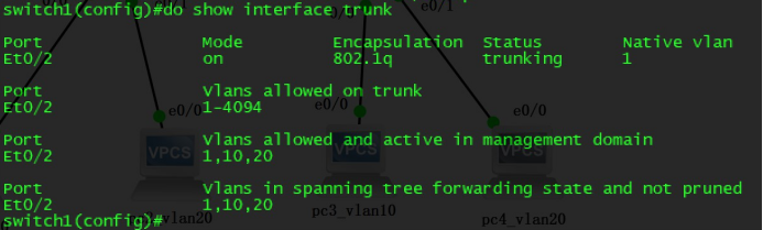
Use the show interface trunk command to test if it will be a success of a trunk link connectivity based on PC.
The host of the same vlan can normally communicate, but different vlan hosts can`t.
Then start to configurate the single-arm routing to achieve communicate. The principle is putting the trunk on the link between switches and routers, then making the router interface encapsulation of ieee802.1q, to tag the corresponding vlan tag while transforming date and bring the address of the interface as a gateway address of the corresponding vlan. Thus we can use the router’s routing functions between different vlans access to each other.
Single-arm routing configuration:
switch1(config)#int e0/3
switch1(config-if)#switchport trunk encapsulation dot1q
switch1(config-if)#switchport mode trunk
switch1(config-if)#exit //trunkFirst the interface between switches and routers configuration for the trunk
router1(config)#interface e0/0
router1(config-if)#no shutdown
router1(config-if)#exit
router1(config)#interface e0/0.1
router1(config-subif)#encapsulation dot1Q 10
router1(config-subif)#ip add 192.168.1.254 255.255.255.0
router1(config-subif)#no shutdown
router1(config-subif)#exit
router1(config)#interface e0/0.2
router1(config-subif)#encapsulation dot1Q 20
router1(config-subif)#ip add 192.168.2.254 255.255.255.0
router1(config-subif)#no shutdown
router1(config-subif)#exit //Enable interface, encapsulate the corresponding vlan tag, and configure the IP address
Test connectivity again
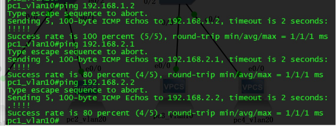
We can see all the IP addresses are connected, which makes vlans visiting each other possible.
CCIE Dumps CCIE Dumps CCIE Dumps CCIE Dumps CCIE Dumps CCIE Dumps CCIE Dumps CCIE Dumps
Experiment 2: using the SVI interface of layer 3 switches to communicate between vlans
The typology:
Background:
SVI interface (exchange virtual interface) , the virtual third-layer interface of vlan in the layer 3 switches can configure the IP address and use the routing of layer 3 switches to realize communication between the vlans. This experiment has the same second-layer basic configuration as the first experiment.However, we should focus on SVI interface configuration on layer 3 switches.
Layer 3 switches configuration:
switch2(config)#ip routing //Open the routing on the layer 3 switches
switch2(config)#interface vlan 10
switch2(config-if)#ip address 192.168.1.254 255.255.255.0
switch2(config-if)#no shutdown
switch2(config-if)#exit //Create vlan20 SVI interface and configure the IP address
switch2(config)#interface vlan 20
switch2(config-if)#ip address 192.168.2.254 255.255.255.0
switch2(config-if)#no shutdown
switch2(config-if)#exit //Create vlan20 SVI interface and configure the IP address
Verify the opening of SVI interface and configured correct IP address
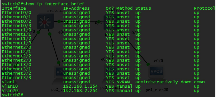
To note here is that keeping SVI interface up has two demands: administrative not be shutdown and an up switch interface within the vlan. If all interfaces within the vlan is down or no any interface being accessed to vlan, SVI interface won`t be up. So if SVI interface is down we can roll out errors according to this tips.
Verify connectivity:
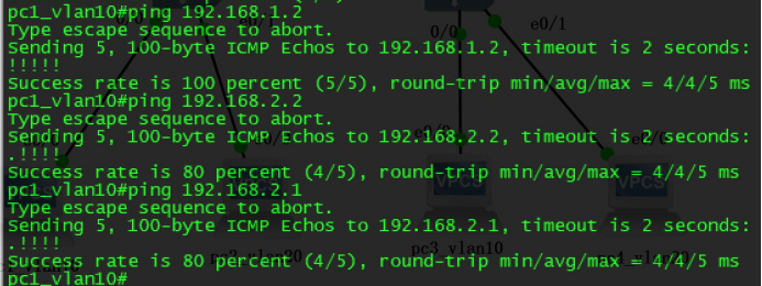
Successful use of layer 3 switches` SVI interface to visit each other between different vlans conclusion:
To sum up, the use of the routing between vlans is both to narrowing the scope of broadcast, and to ensure that the host can communicate with each other within the network. There are two ways to achieve routing between vlans: one is in the layer 2 switch we can use the single-arm routing encapsulated with 802.1 q to communicate between vlans; another is to communicate with the SVI interface of the layer 3 switches if the layer 3 switch exists in the network. Due to both ways configured gateway address on a host computer to transform packages to the gateway, and realize visiting between vlans after routing transmission, these two are collectively referred as routing technology within vlans.
Here is a thinking: if the experiment only configure the IP address not the gateway, then can the hosts normally communicate between different vlans? If they can, what`s the principle?
Get a quick discussion with your friends!
CCIE Dumps CCIE Dumps CCIE Dumps CCIE Dumps CCIE Dumps CCIE Dumps CCIE Dumps CCIE Dumps